1. Overview of the EEG Electrode-Skin Interface & Impedance Physics
In electroencephalography (EEG) acquisition, the term "impedance" is ubiquitous. Clinicians and researchers routinely check contact quality before recording, striving to reduce impedance below standard clinical thresholds—typically $5\text{ k}\Omega$ or $10\text{ k}\Omega$. However, from a rigorous bio-instrumentation and circuit theory perspective, the physical quantity measured at the scalp is not purely resistive, nor is it a simple static scalar. It is a complex, frequency-dependent electrochemical boundary impedance $Z(\omega)$ governing charge transport between ionic neural currents in tissue and electronic conduction in copper leads.
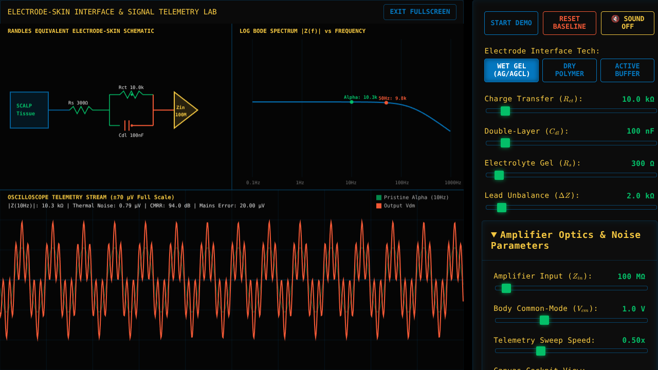
The human skin stratum corneum consists of dead, keratinized epidermal cells acting as a dielectric barrier. When an electrode (such as silver/silver chloride, $\text{Ag/AgCl}$) is coupled to the scalp via an electrolyte gel containing $\text{Cl}^-$ ions, an electrical double layer forms at the interface. This boundary acts simultaneously as a charge-transfer resistor ($R_{ct}$), a non-faradaic capacitive layer ($C_{dl}$), and a bulk electrolyte solution resistor ($R_s$), forming the classical Randles Equivalent Circuit Model.
Understanding how this non-linear boundary interacts with the instrumentation amplifier's input impedance ($Z_{in}$) and Common Mode Rejection Ratio ($\text{CMRR}$) is crucial. High electrode impedance not only attenuates weak microvolt-level cortical signals ($10 - 100\,\mu\text{V}$), but more critically, impedance unbalance ($\Delta Z$) between differential lead pairs converts benign common-mode environmental noise (such as $50\text{ Hz} / 60\text{ Hz}$ power line hum) directly into differential-mode signal corruption.
2. How to Use the Impedance & Signal Quality Laboratory
This interactive simulator allows you to manipulate biophysical electrode parameters, electrolyte properties, and amplifier characteristics in real time to observe their direct effect on complex impedance $|Z(f)|$, thermal noise generation, and common-mode artifact conversion.
- Tri-Panel Cockpit: The unified cockpit visualizer displays all three crucial diagnostic views simultaneously: the animated Randles Circuit diagram with parallel charge flow (top-left), the logarithmic frequency Bode plot (top-right), and the live differential oscilloscope stream (bottom).
- Electrode Interface Technology Toggle: Alternate between Wet Gel ($\text{Ag/AgCl}$) (low $R_{ct}$, high $C_{dl}$), Dry Polymer (high $R_{ct}$, low $C_{dl}$, subject to motion baseline drift), and Active Buffer electrodes. Observe how active buffers place an ultra-high impedance Unity-Gain Operational Amplifier directly at the scalp site, eliminating lead mismatch noise.
- Charge Transfer Resistance ($R_{ct}$): Adjust the non-faradaic electrochemical resistance from $1\text{ k}\Omega$ to $100\text{ k}\Omega$. Notice how higher resistance elevates low-frequency impedance and increases intrinsic Johnson-Nyquist thermal noise.
- Double-Layer Capacitance ($C_{dl}$): Scale capacitive charge storage at the double layer ($10\text{ nF} - 1000\text{ nF}$). Increasing capacitance reduces overall impedance at higher frequencies ($>10\text{ Hz}$) due to decreasing capacitive reactance $X_C = \frac{1}{2\pi f C_{dl}}$.
- Lead Impedance Unbalance ($\Delta Z$): Adjust the mismatch between Electrode A and Electrode B from $0\text{ k}\Omega$ to $30\text{ k}\Omega$. Watch how even a modest mismatch rapidly degrades the amplifier's effective CMRR, causing $50/60\text{ Hz}$ mains noise to swamp the underlying cortical Alpha rhythm ($10\text{ Hz}$).
- Amplifier Input Impedance ($Z_{in}$): Vary amplifier input impedance from $10\text{ M}\Omega$ to $2\text{ G}\Omega$. High $Z_{in}$ buffers the system against mismatch artifacts, demonstrating why modern bio-potential DAQs utilize gigaohm-range FET inputs.
- Telemetry Sweep Speed: Adjust the oscilloscope scrolling cadence between $0.10\times$ (slow clinical sweep) and $1.50\times$ (rapid monitor flow) for optimal visual clarity.
3. Mathematical Underpinnings, Equivalent Circuits & DSP Degradation
The total complex impedance $Z(\omega)$ of the Randles equivalent electrode-skin model as a function of angular frequency $\omega = 2\pi f$ is expressed mathematically as:
$$Z(\omega) = R_s + \frac{R_{ct}}{1 + j \omega R_{ct} C_{dl}} = R_s + \frac{R_{ct}}{1 + (\omega R_{ct} C_{dl})^2} - j \frac{\omega R_{ct}^2 C_{dl}}{1 + (\omega R_{ct} C_{dl})^2}$$
The magnitude of the complex impedance $|Z(\omega)|$, which is what commercial EEG impedance meters display at a single test frequency (typically $20\text{ Hz}$ or $30\text{ Hz}$ sinusoidal AC to avoid electrode polarization), is given by:
$$|Z(\omega)| = \sqrt{\left(R_s + \frac{R_{ct}}{1 + (\omega R_{ct} C_{dl})^2}\right)^2 + \left(\frac{\omega R_{ct}^2 C_{dl}}{1 + (\omega R_{ct} C_{dl})^2}\right)^2}$$
Thermal Johnson-Nyquist Noise: High real resistive impedance components ($\text{Re}(Z)$) generate intrinsic thermal voltage noise $v_n$, governed by Nyquist's equation over measurement bandwidth $\Delta f$:
$$v_n = \sqrt{4 k_B T \cdot \text{Re}(Z) \cdot \Delta f}$$
Where $k_B \approx 1.38 \times 10^{-23}\text{ J/K}$ is Boltzmann's constant and $T$ is absolute temperature ($310\text{ K}$ at body temperature).
Common-Mode Artifact Voltage Conversion: Environmental electromagnetic fields induce a common-mode voltage $V_{cm}$ across the human body (often several volts). The differential instrumentation amplifier receives inputs through Lead 1 ($Z_1$) and Lead 2 ($Z_2 = Z_1 + \Delta Z$). The resulting common-mode error voltage $V_{cm\_error}$ injected into the differential channel is derived as:
$$V_{cm\_error} = V_{cm} \cdot \left( \frac{Z_1}{Z_1 + Z_{in}} - \frac{Z_1 + \Delta Z}{Z_1 + \Delta Z + Z_{in}} \right) \approx V_{cm} \cdot \frac{\Delta Z}{Z_{in}}$$
This equation reveals why absolute impedance is less dangerous than impedance unbalance ($\Delta Z$). A system with two balanced $20\text{ k}\Omega$ electrodes ($\Delta Z = 0$) produces a cleaner differential EEG signal than a system with one $1\text{ k}\Omega$ electrode and one $10\text{ k}\Omega$ electrode ($\Delta Z = 9\text{ k}\Omega$).
4. Clinical Neurophysiology & Next-Generation Electrode Engineering
In clinical neurology (routine scalp EEG, ICU continuous monitoring, and long-term epilepsy monitoring units), maintaining low impedance via skin abrasion and chloride gel application is labor-intensive and prone to gel drying over 24-48 hours. Drying gel causes $R_s$ and $R_{ct}$ to skyrocket, introducing baseline drift and signal dropouts.
Next-generation neurotech architectures address these biophysical limitations through two primary engineering innovations:
- Active Electrodes: Placing ultra-low-noise FET operational amplifiers directly inside the electrode cap housing provides near-zero output impedance over the transmission wire, rendering the system immune to cable movement artifacts and lead mismatch.
- Ultra-High $Z_{in}$ Active Front-Ends: Utilizing CMOS/Gigaohm instrumentation amplifiers ($Z_{in} > 10\text{ G}\Omega$) allows accurate EEG acquisition even through dry capacitive sensors or micro-needle epidermal arrays with contact impedances exceeding $100\text{ k}\Omega$.
Open Access License: This interactive educational module is released under
CC BY-NC 4.0 (Attribution-NonCommercial)
for non-commercial research, academic study, and clinical education.
Commercial & Enterprise Licensing: For white-labeling, proprietary LMS/course embedding, hardware dashboard telemetry integration, or custom feature engineering, secure a commercial license at
BioniCloud.com or contact
Dr. Yuri Beno.